92 Results
View results:
Sort by:
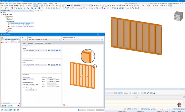
State of Development of Beam Panel
What is the current state of development of the "beam panel" element for modeling timber frame walls?

Question
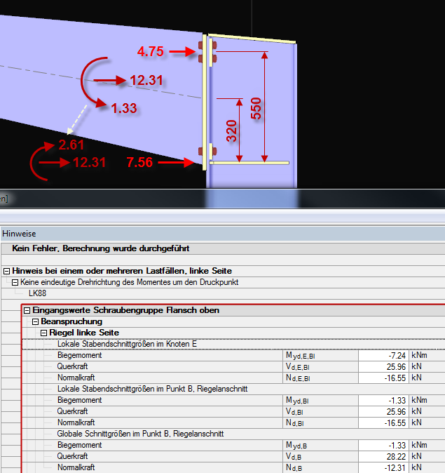
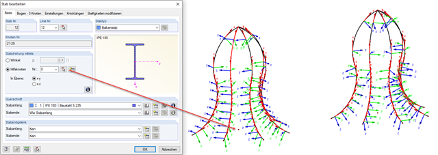
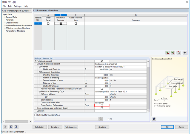
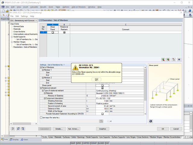
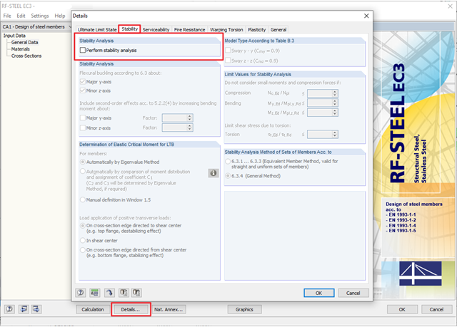
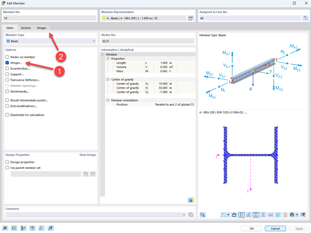
Where do I find the connection moments due to the applied rotational restraint in RF‑/STEEL EC3?
Question
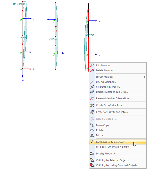
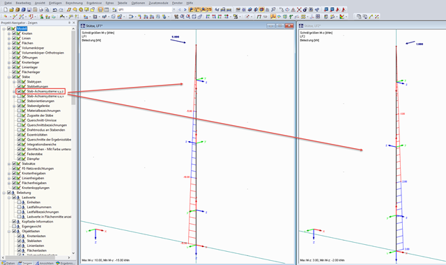
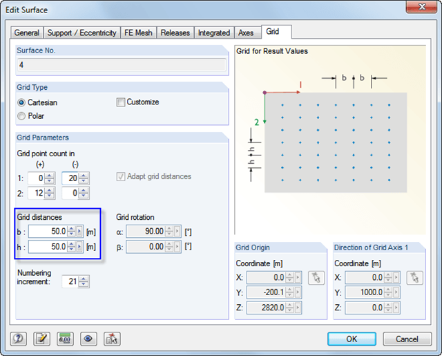
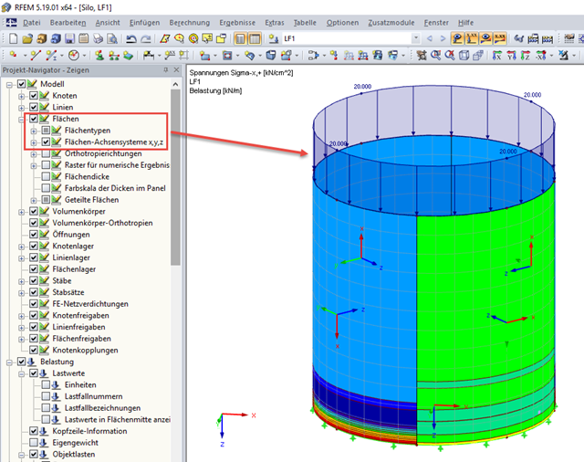
I am calculating a symmetric surface model. However, the resulting stresses are not consistent. Have I done something wrong?
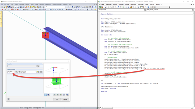
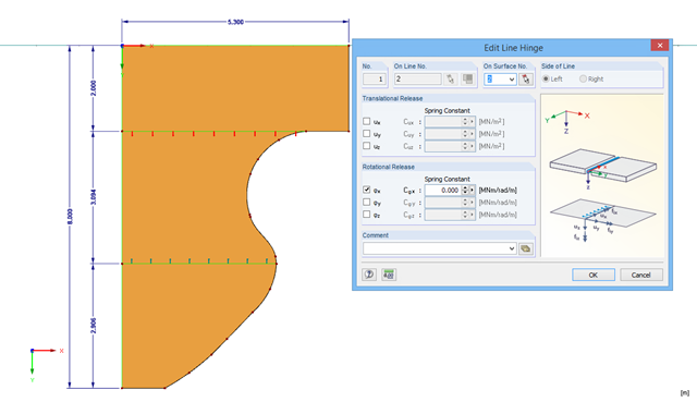
Creating Nonlinear Line Hinge with Python
How can I create a nonlinear line hinge with the Python program?